


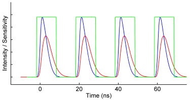

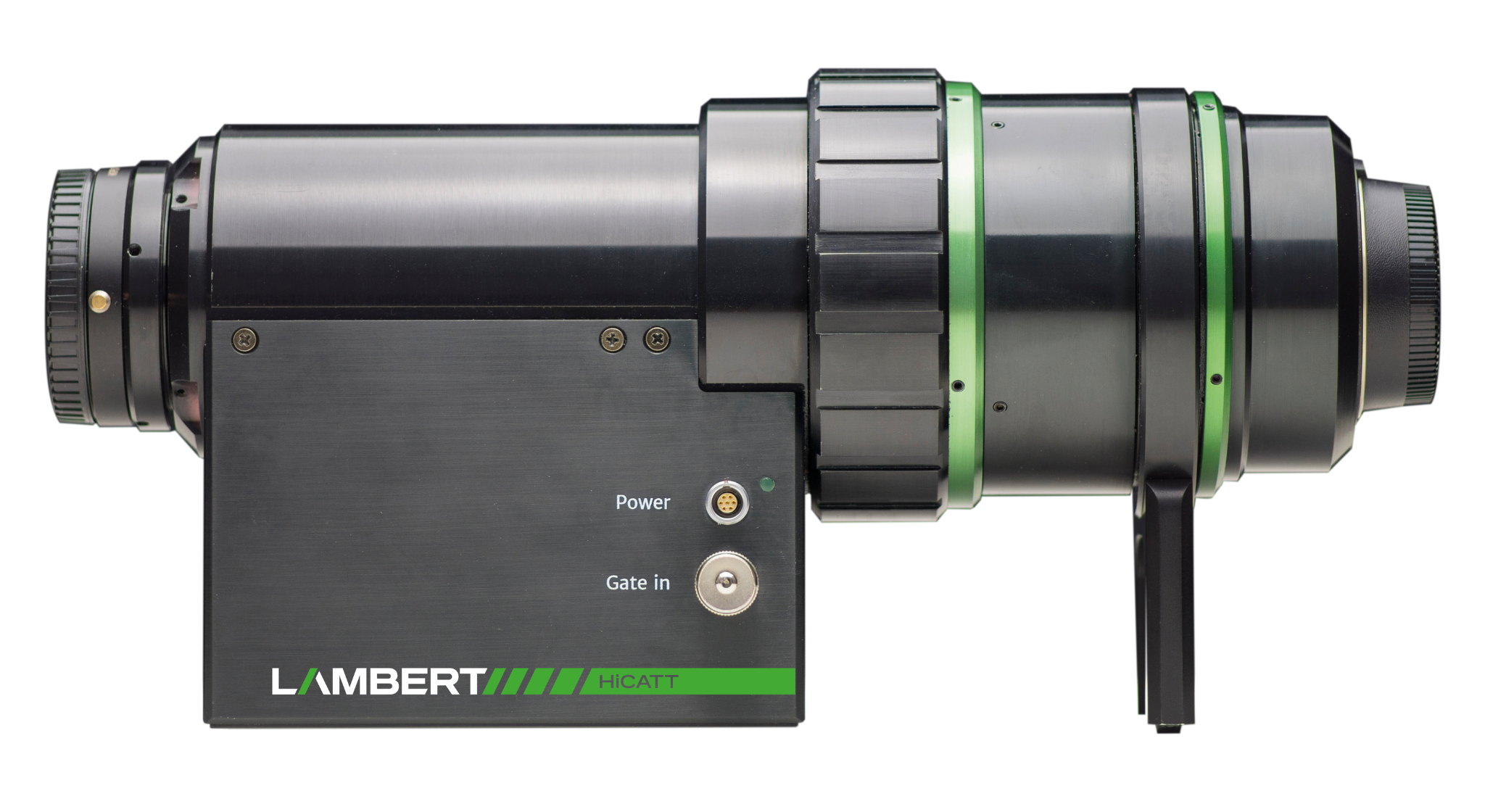
The High-speed Intensified Camera Attachment (HiCATT) is designed for use with a high-speed camera. It increases the sensitivity of your camera and enables low-light imaging at frame rates up to 1 MHz (10 Mhz in burst)
View Product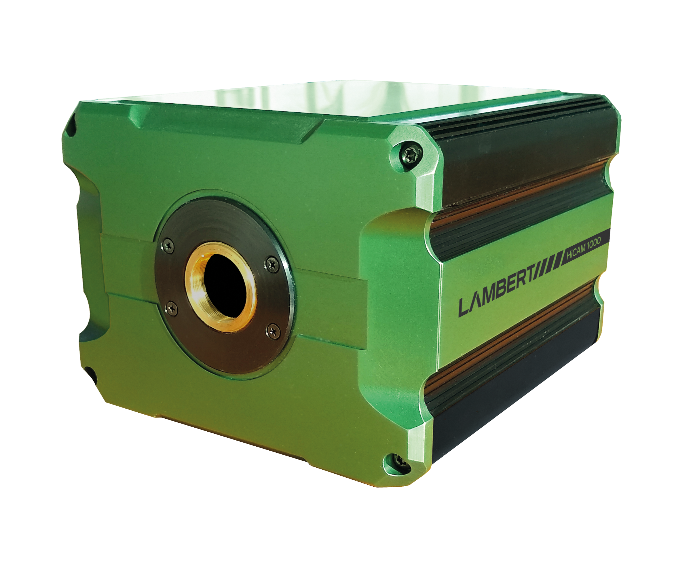
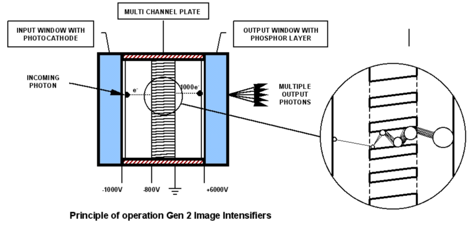
The HiCAM is a gated intensified high-speed camera. It has an integrated fiber-optically coupled image intensifier, which offers a unique combination of high speed and sensitivity down to single photon level. Because the HiCAM does not need high intensity light sources, it is suitable for use in low-light level conditions.
View Product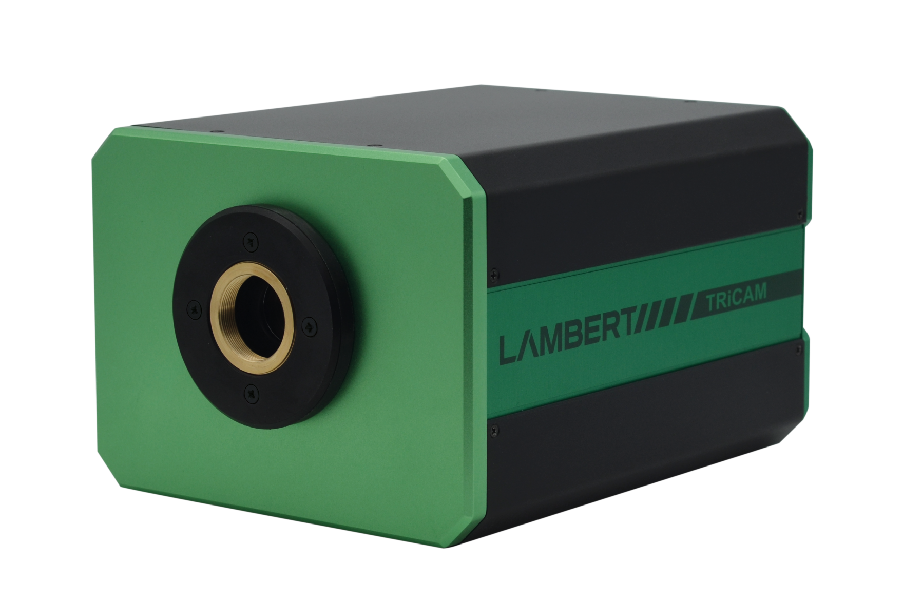
The TRiCAM is a compact intensified camera. It is designed for scientific and industrial applications that require low-light imaging. With built-in signal generators, the TRiCAM is capable of ultra-short exposures through fast gating and therefore suitable for time-resolved imaging.
View Product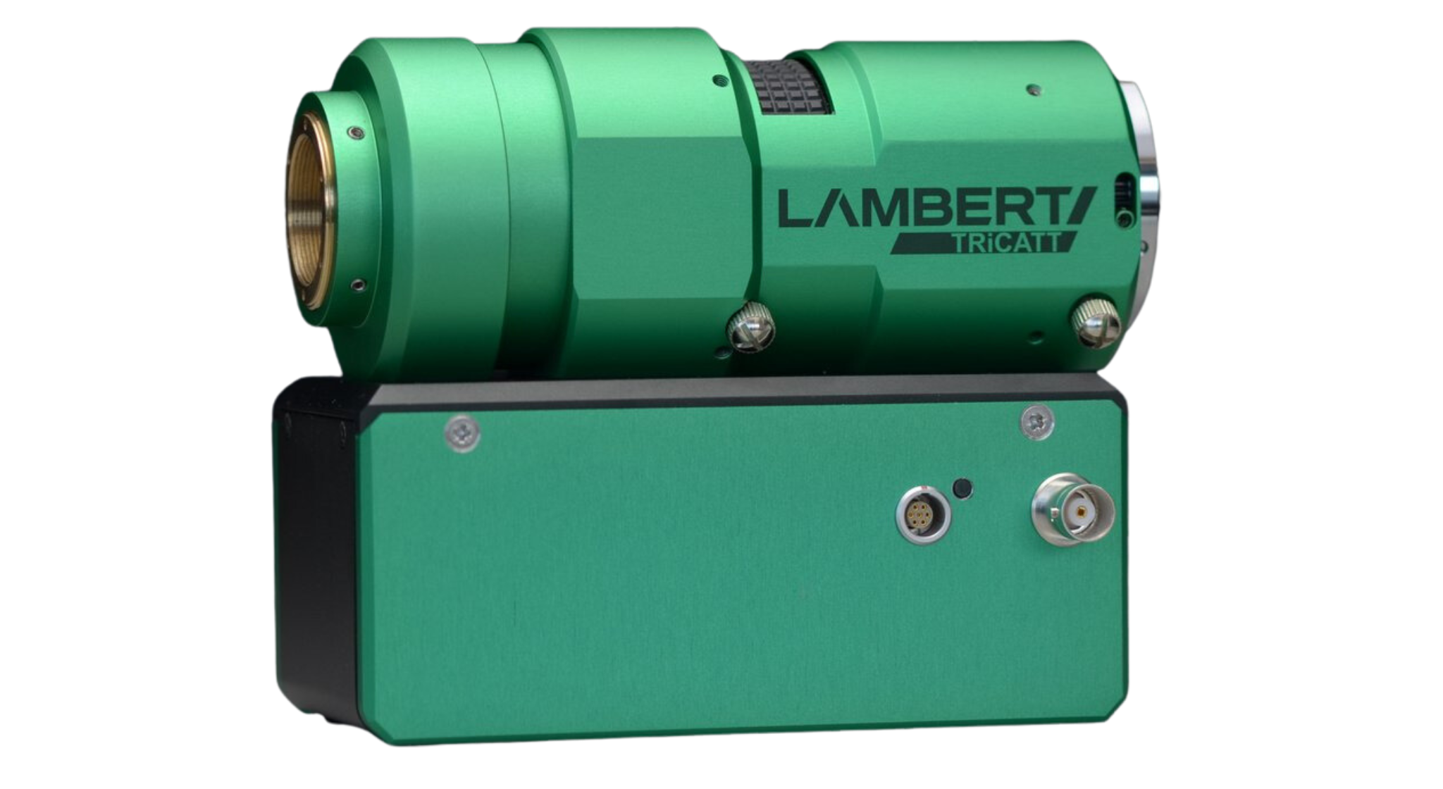
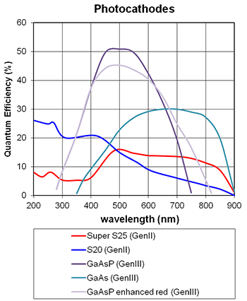
The TRiCATT is a compact lens-coupled image intensifier for scientific and industrial applications that require: – Low-light level imaging – Ultra-short exposures through fast gating – Frequency-domain imaging using lock-in detection Any camera with C-mount and a 1/2″, 2/3″, or 1″ image sensor is compatible with the TRiCATT. You can find the right TRiCATT for your camera with our interactive calculator.
View Product
The High-speed Intensified Camera Attachment (HiCATT) is designed for use with a high-speed camera. It increases the sensitivity of your camera and enables low-light imaging at frame rates up to 1 MHz (10 Mhz in burst)
View Product
The HiCAM is a gated intensified high-speed camera. It has an integrated fiber-optically coupled image intensifier, which offers a unique combination of high speed and sensitivity down to single photon level. Because the HiCAM does not need high intensity light sources, it is suitable for use in low-light level conditions.
View Product
The TRiCAM is a compact intensified camera. It is designed for scientific and industrial applications that require low-light imaging. With built-in signal generators, the TRiCAM is capable of ultra-short exposures through fast gating and therefore suitable for time-resolved imaging.
View Product
The TRiCATT is a compact lens-coupled image intensifier for scientific and industrial applications that require: – Low-light level imaging – Ultra-short exposures through fast gating – Frequency-domain imaging using lock-in detection Any camera with C-mount and a 1/2″, 2/3″, or 1″ image sensor is compatible with the TRiCATT. You can find the right TRiCATT for your camera with our interactive calculator.
View Product

5th floor,
Leonard Springerlaan 19
9727KB Groningen
The Netherlands